Engineering Portfolio
Professional, Class Work, and Personal Projects


Re:Build Fikst
Wilmington, MA
July 2020 - Present
Bringing New Products to Life
I have been working at Fikst Product Development since 2020 as a Senior Mechanical Engineer. Fikst is a member company of Re:Build Manufacturing, and we are a product development firm specializing in mechanical engineering and embedded systems consulting for companies in a variety of industries including healthcare, industrial automation, security, consumer products, etc.

Featured Projects
SightDx
I spent a few years working on the Sight OLO device. This is a desktop-sized blood analyzer which uses two drops of blood in a medical consumable cassette to conduct a complete blood count (CBC) test. Our team supported Sight in improving the design of the consumable cartridge as well as the internal electromechanical components inside the OLO device.
Evolv Technology
I worked with Evolv to support the design of their weapons-screening system, the Express.
Evolv Express® uses advanced sensor technology and artificial intelligence to distinguish between weapons and everyday items. It improves security by reliably detecting threats and enables a directed search, leading to a more dignified and respectful screening process that empowers security professionals and enhances the visitor experience.

Holiday Puzzle
For the last five Holiday seasons, I have had the privilege of project managing our annual Holiday Puzzle Project. Fikst has a tradition of sending these puzzles as a thank you to clients at the end of each year. Each year we challenge ourselves to try something new. We begin by brainstorming with a wide group of engineers, and then a smaller team of 4-5 engineers selects a concept and designs the puzzle. Once the puzzle is designed, we pull in a wider group once again to build the puzzles and send them out to our clients!


TERRAFUGIA
Woburn, MA
September 2013 - June 2020
Building a Flying Car

The Transition
The Transition is a Light Sport Aircraft whose wings fold to allow the vehicle to be legally driven on the road.
Some of the skills I’ve learned at Terrafugia are:
Component design and material selection
Design for manufacturing and assembly
Design for human interaction, ergonomics and aesthetics
Managing supplier contracts
Interpreting ASTM F2245 (LSA) standards and CFR 49 571 (FMVSS) regulations
I was the Manager of the Interior and Restraints team. In addition to supervising 2 full-time engineers, I was the project owner of the dashboard, interior trim, seats, seatbelts, and HVAC systems of the vehicle. This means I was in charge of overseeing their designs, planning builds and testing, managing schedules, and managing vendor contracts.
At right is a render of the interior of the vehicle that was developed as a collaboration between myself and an aircraft interiors vendor.


In 2016, I spent some time working on conceptualizing the TF-X, which is a successor to the Transition vehicle. I created this logic drawing to illustrate an occupant packaging concept and benchmark it against an existing vehicle.

PRATT & WHITNEY
East Hartford, CT
June 2011 - August 2013
Oil Systems Analyst
Military Jet Engines
From 2011-2013, I worked at Pratt & Whitney as a Lubrication Systems Analyst. Our group focused on system level operation for jet engine oil systems.
The Systems Analysis group is responsible for creating and maintaining computer models to simulate oil system operation during the engine design process. A lot of focus on jet engine design is placed on the aerodynamics, but equally as important are the bearings that support the engine shafts. The oil system must be designed such that bearings receive certain minimum oil flows. Making this more challenging are varying speeds, pressures, and air flows over different aircraft operating conditions.


We were also responsible for monitoring oil system health during engine testing. We tested engines for a variety of reasons, from certification, to matching data to our computer models, to advanced engines that provide learning about something we've never done before. During my time with the company, I was fortunate enough to travel to cover engine testing. This was definitely one of the most high energy parts of the job, which included being on a headset in the control room monitoring engine health and making recommendations on the fly.
Additionally, another task I was responsible for was debugging issues with the oil system during production and on fielded engines. Given data downloads from the engine, we were responsible for pinpointing which part of the system might be causing problems.

Patents


Gas Turbine Lubrication Systems
This patent from my time at Pratt & Whitney pertains to the operation of a valve in the oil scavenge line of a jet engine.
In a jet engine, the shaft bearings are contained within bearing compartments which are cooled with oil. The oil enters through oil jets which spray the bearings, and leaves the compartment through what is called a scavenge line. Scavenge lines typically contain a valve which can be either open or closed to regulate the pressure inside the bearing compartment based on the operating condition.
My patent is for a continuously variable scavenge valve which can precisely adjust the scavenge line pressure drop based on shaft speed. This would increase overall efficiency of the engine, and thus increase fuel economy.
Filed October 2013, Issued September 2018
Electronic Gear Shifter Assembly
This patent is from my time at Terrafugia, and it is a gear shift lever which is designed to operate as a standard gearshift lever with standard automotive positions, but also contain a flight position in a second shift line with the ability for an operator to simply control the altitude by pushing the shifter lever up or down.
In another variant, the shifter may be used as the control with which an operator can fold and unfold the wings of the vehicle.
Filed April 2016, Issue Date Pending

2.007 Robotics Class
Spring 2009
Can Crushing Robot
Wall-E Robotics Competition

This project was the main project for a class, 2.007, Design and Manufacturing I. In this class, the robots were built individually rather than on teams to ensure each engineer has a firm grasp of hands-on engineering principles.
The competition our year was “Wall-E” themed, and each robot could score points a variety of different ways from stacking bales of trash in a scoring area to crushing soda cans and placing them in a storage slot. Each student was provided with a standard kit of parts. We were allowed to use the only the kit of parts or recycled materials to construct our robots.
My design process always began with developing concept sketches in my design notebook. Once I had narrowed down the design possibilities, I would create a SolidWorks assembly model to see what the geometry would look like before cutting any metal. Finally, I'd create drawings and get to work building the design in the machine shop.
Because of the high point values associated with crushing the soda cans, I set about designing a robot capable of the task. Bench level testing showed that a single can requires 150 lbs of vertical force to crush a can.
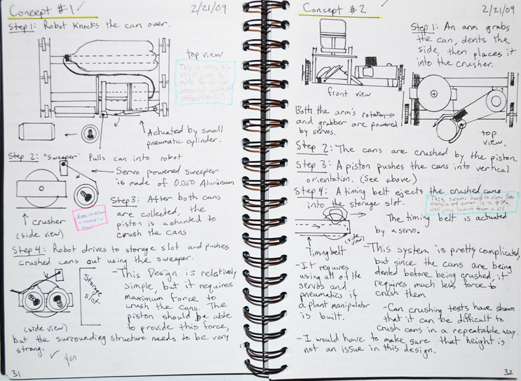
A variety of can-crushing methods were developed, but I ultimately decided on a custom pneumatic piston made from a peanut butter jar. With the large piston area, the crusher had enough force to crush 2 cans at once. In the class of over 100 students, this was the only design capable of such a task.
The next step was to develop a drive base to collect the cans from the playing field. Unfortunately the can crusher was too large to transport using the servos provided in the kit, so the next option was to have the drive base collect the cans and return them to the crusher.
I designed a basic six wheeled drive base with a simple arm capable of picking up a can and returning it to the crusher.
The drive base itself was hooked up to take input from a remote control, while the can crusher was programmed via microcontroller to activate the pneumatic piston at the press of a button.
Ultimately, due to the single elimination nature of the final competition, my robot did not proceed to the next round. A combination of excess friction in my custom gearboxes, weak servos, and poorly charged batteries led to a very slow drive base during the competition, and I was unable to score points.
Despite an elimination at the competition, I learned valuable skills ranging from maintaining a detailed design notebook to CAD work to precision machining to debugging.


2.008 Yoyo
Spring 2010


Yoyo Project
The Yoyo was the main class project for 2.008, Design and Manufacturing II. The focus of this project was to get a feel for the intricacies of mass manufacturing by requiring each team to produce 100 yoyos.
After some careful consideration, our team decided on a whimsical Hungry, Hungry Hippos themed yoyo. In addition to playing with it as a yoyo, the user can attempt to get each of the four little balls in the side into the hole for each of the hippo heads.
The yoyo contains 4 different injection molded pieces and one thermoformed dome. The team designed the whole yoyo in Solidworks first, followed by also designing the molds themselves. Given the thermal complexities involved in injection molding and thermoforming, care was taken to ensure that once the parts came off the mold they would shrink to the intended size.

2.008 Paperweight
Spring 2010
Paperweight
The paperweight was the first project in the class 2.008, Design and Manufacturing II. We were given an aluminum disk, approximately 3/4" thick and 3" in diameter. The goal was to CNC machine our own custom design into the part.
I chose to pay homage to my favorite musical, [title of show]. "Die, Vampire, Die!" is a reference to a song in the show. In the show, a vampire is defined as an person, thought, or feeling that stands between you and your creative self-expression.
The initial design was worked out in SolidWorks, and then the drawings were imported into MasterCam to create toolpaths for both the CNC mill and lathe. Given the complexities of the design, care was taken to minimize the number of tools required as well as the number of tool changes during the process plan.
The outer profile was turned on the CNC lathe, and the face designs were done on a CNC mill.

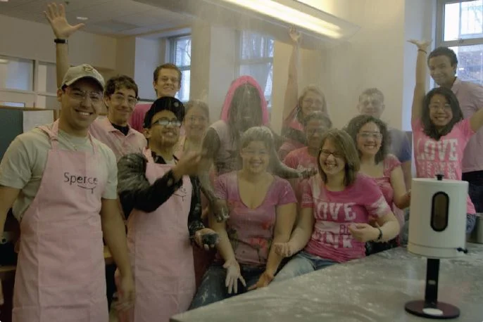
2.009 Product Design
Fall 2010
2.009 Pink Team
Spence, the Sensible Dispenser
Spence (The Sensible Dispenser) was a flour canister and dispenser that was built as the main class project for 2.009, Product Design. The class goal was to emulate the environment of a Product Design firm as closely as possible. Each team was made up of 20 students.
Given the broad theme "food," each team began by generating hundreds of product concepts. Ideas were diverse, and included things like food harvesting, processing, packaging, storing and cooking, among others.
Some of the early concepts our group continued developing included a computer controlled cake decorator, a weighted egg shaped trash can that couldn't fall over, and a sprinkle gun for decorating cakes. Ultimately, our team selected the flour dispenser as the concept most valuable to a customer and feasible to complete within the span of the class.

Me presenting our product to the class

Sketch model prototypes

Our final prototype
The projects were developed to meet several major milestones, going from sketch models to a tech review, and ultimately a final presentation to a large audience (1000+) including faculty, students, industry professionals and the general public.
A lot more than technical function is at stake in product design. Industrial design and user interface also play major roles. We created sketch models of different user interfaces to test with different customers, shown to the left.
Additionally, a lot of effort was put into product aesthetic, branding, and how to present the product to potential customers.

2.72 Benchtop Lathe
Spring 2011

Benchtop Lathe
The benchtop lathe was the class project of 2.72, Precision Machine Design.
Each group of six built a benchtop lathe capable of machining materials as hard as steel to precise tolerances. In addition to performing, the lathes had to be rugged. At the end of the class, the lathes were pitted against each other in a cutting speed competition and a death test (sledgehammers were involved).


In addition to the design, machining, and assembly, we were required to do detailed structural and thermal analysis of the parts.
The class was set up to emulate a company setting as closely as possible. Each member of the group had one specialty (i.e. measurement, machining, etc.) My specialty was the CAD work and drawings. We had to complete our analyses as well as detailed process plans and drawings before any parts could be manufactured.
Additionally, we focused closely on assembly processes and how the parts interacted with each other. It is key to avoid over-constraint in a machine this complicated. One over-constraint challenge we faced was between the lead screw and rail bushings. We solved this problem by designing a flexure to attach the carriage to the lead screw. The flexure was stiff in the axial direction of the lead screw, but had some play in the radial direction.
This project definitely gave me an appreciation for the fine details of engineering, and how something as seemingly insignificant as a 0.002" tolerance can mean the difference between a lathe that works correctly and one that doesn't.
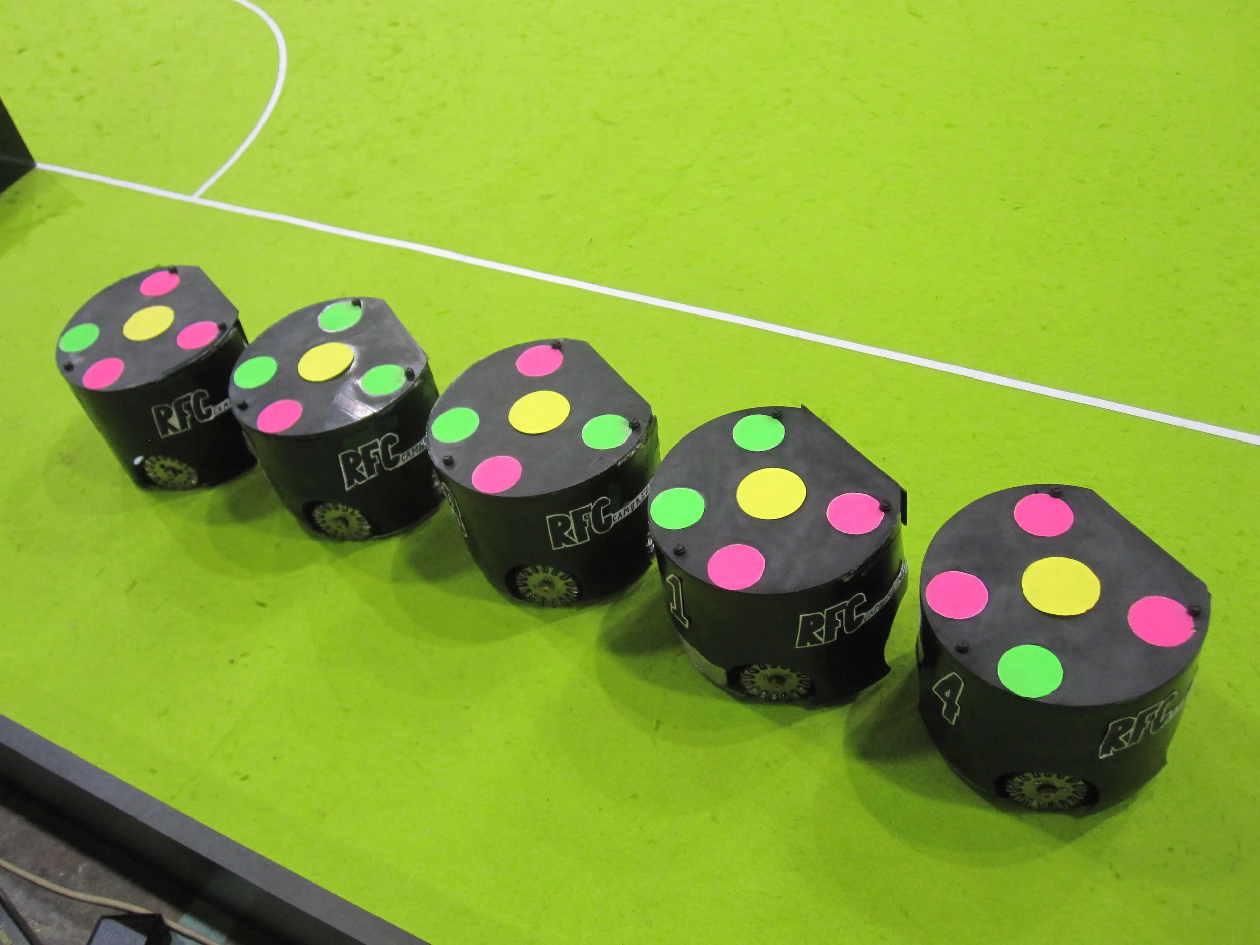
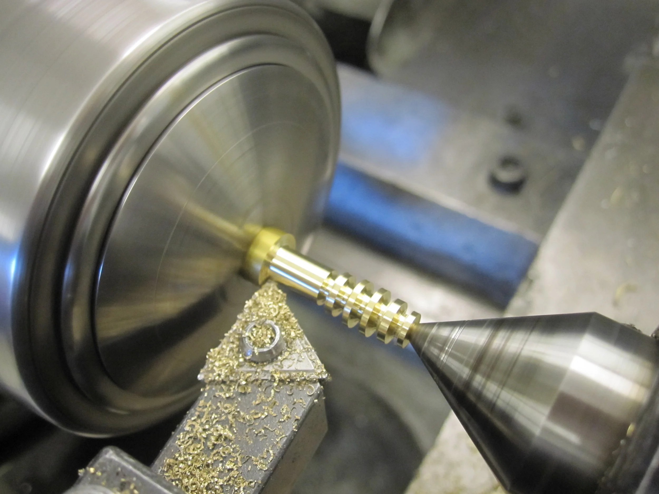
MIT/Harvard Robocup Team
Fall 2007-Spring 2011
Robocup

A robot with it’s shield removed
During my four years at MIT, I was a part of the MIT/Harvard RoboCup team. I was on the mechanical sub-team. In addition to this technical work, junior year I became Treasurer, and senior year, I became President of the team.
RoboCup is an international robotics competition with many divisions within it, but we competed in the Small-Size autonomous soccer league. The organization was founded to advance the field of robotics through friendly competition. In addition to fielding a team of robots, every year the teams write a team description paper to document any engineering breakthroughs.
In the Small-Size league, teams of five robots each play against each other. The robots are about eight inches in diameter, and eight inches tall. They compete with a standard orange golf ball.

The team competed in Istanbul, Turkey in July 2011

An exploded view of the latest omni wheel design
Each year we are allowed to build off the work of the previous year, so a lot of what we did was redesign modules on the robot to achieve performance benefits. A project I worked closely on my Senior year was to redesign the omni wheels.
A global vision system above the field reads the colorful dot pattern on top of each robot and sends the information back to each team. A computer program then determines the strategy and sends instruction to each robot. Human controllers only need to tell the computer when to stop and start play.

Evolution of the wheel design. Original on the left, iterations middle and right

Final omni wheel design
We were having a lot of trouble with the wheels before our redesign. Previously, the wheel shafts had been aluminum shafts press fit into aluminum plates. We ran into a host of issues ranging from deformed shafts and failed press fits to gears not meshing and wheels wobbling, so we decided it was time to make a change to something more robust.
Also the previous design of many thin rollers was causing the driving of the robots to be very noisy, so we decided to try moving to a wider roller design.
Our new shaft solution was to switch from the press fit aluminum to brass shoulder bolts. This proved significantly more repeatable, and the tolerances on the shoulder were much tighter than on a press fit aluminum shaft.
In addition, new wheels were manufactured with extreme care taken to ensure that we CNC machined the center pockets in the exact center of the wheels, not an easy feat when the wheel bodies themselves are fabricated on the waterjet, and they are not round.
It turned out that the new rollers, while they may have worked on a smooth surface, on a felt surface, the metal tabs between rollers scraped on the felt of the field. This resulted in a new design, shown to the left. The rollers were still wider to provide a smoother ride, but larger in diameter to keep the metal tabs off the felt.
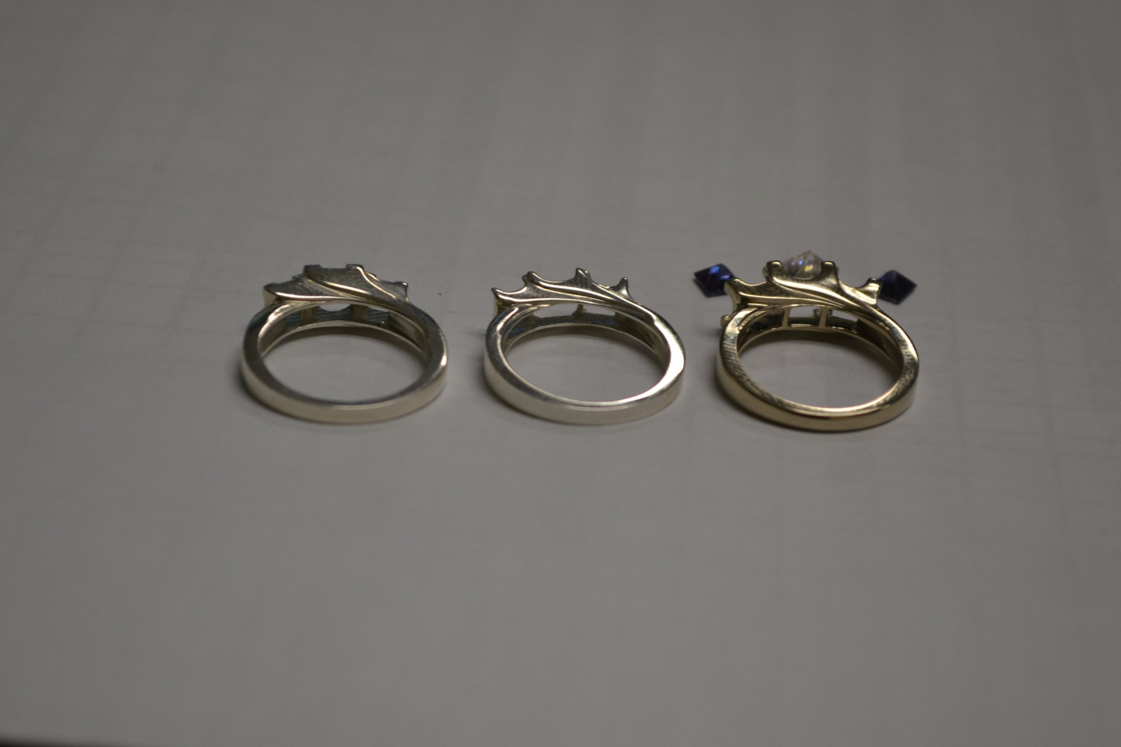
Engagement Ring
Fall 2015
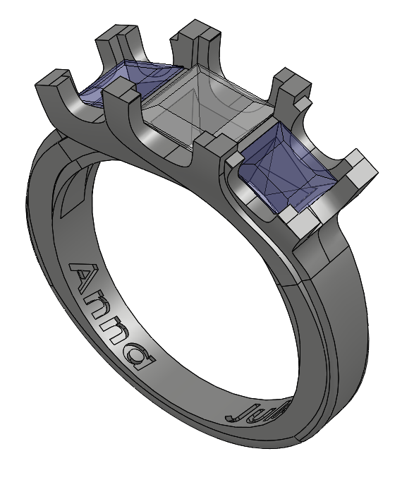
Solidworks model of ring
Engagement Ring
I knew I wanted my proposal to my wife to be unique to me and my skillsets, so I decided to design her engagement ring using SolidWorks.
I had a couple of key requirements. First was that we wanted to buy conflict-free stones. Second, she wanted something simple that wouldn’t catch on anything. Third, she expressed interest in Alexandrites, a stone which changes color depending on the light it is viewed in.
I found a 3D printing company called i.materialise that 3D prints wax blanks which can be cast in different metals.
I ended up printing 2 prototypes in silver. I took the second prototype to a local jeweler for feedback before printing the final ring in white gold.

Left and Middle: First and second silver prototypes; Right: Final white-gold ring

Final ring with stones placed in before being set by the jeweler

Electric Guitar Build
January 2011 - August 2013

Electric Guitar Build
In January 2011, I took a class with the MIT hobby shop, in which we learned to build an electric guitar.
I envisioned a bright green stratocaster with a flame maple top. I’m thrilled that it came out exactly how I had envisioned it.


Cryptex
Spring 2010


Cryptex
Ever since I had seen The Da Vinci Code, I'd always wanted to build my own crypetx. For those who haven't seen the movie or read the book, a cryptex is a cylindrical puzzle with rotating rings with letters on them. Only when the user rotates all five rings to the correct letter sequence will the puzzle unlock and slide open, revealing a secret storage chamber.
I began building the Cryptex as a culmination of a scavenger hunt I put together for a friend. After putting together several clues, she discovered that the Cryptex opens with the word "LIGHT" as seen above.
The Cryptex was machined almost entirely on the lathe out of scrap delrin plastic I had floating around. The white of the plastic was not quite appealing so a couple coats of black and gold paint added a nice touch.
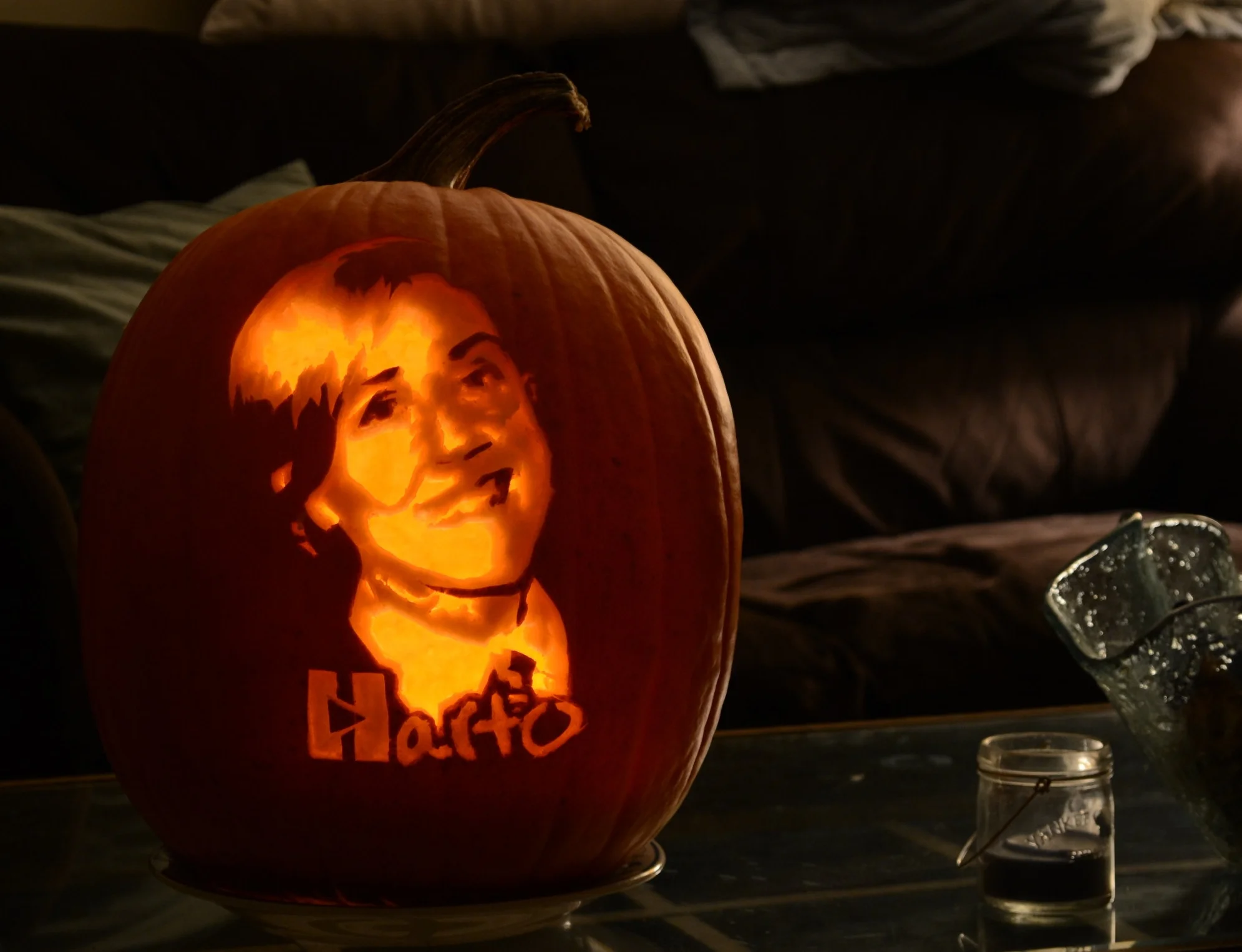
Pumpkin Carvings
Fall 2008 - Present


Pumpkins
One seasonal activity I've discovered that appeals to my sense of creativity is carving pumpkins. I usually create my own patterns in Photoshop since I like to make one-of-a-kind creations.
The image to the left shows an image I took from the Internet and transformed into a three tone vectorized template ready to carve.
I find it satisfying to take the time to meticulously carve out a pattern. While carving, the shapes don't seem to look like anything, but once you put the candle inside, the pattern comes to life and takes the shape of what you intended to carve.


New London Travel Poster
December 2021
One year, I decided to make something special for my parents for Christmas. I have always loved the idea of using multiple layers of laser cut material to create something dynamic and interesting, and after browsing around Etsy for some ideas, I settled on doing a travel poster. My parents are from New London, CT, and we have always loved the Ledge Lighthouse.
I set about creating some artwork in Inkscape, using some photos from Google images as reference.

Inkscape art file with colors

Inkscape art file, converted to laser-cut paths and raster regions

Laser Cutting. The material is 1/8” baltic birch.

Individual laser cut layers

Stack of laser-cut layers

Complete with wood dye and shellac